Real-time Precise Satellite Navigation Device using RTS Correction with Bidirection LSTM Algorithm
- Reference: M.S. Dissertation
- Analysis of a Signal of the IGS RTS Correction for Determining Prediction Models for Signal Loss
- Porting and Devising Algorithms for Prediction and Detection for Signal Loss
o Developed Device
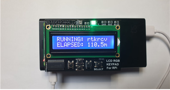
Left: Running State of RTKRCV being able to be confirmed by LCD Keypad.(First Line: Program Name, Second Line: Elapsed time to Execute RTKRCV.)
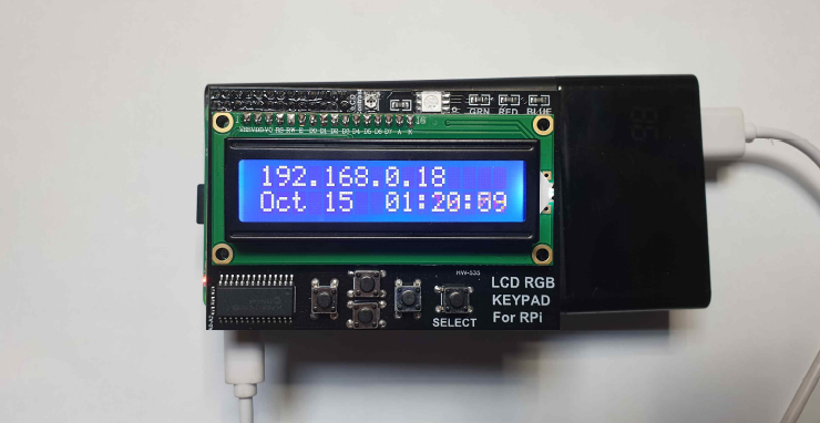
Right: Waiting State(First Line: Internal IP Address, Second Line: Date and Time)
o Analysis of Prediction Models
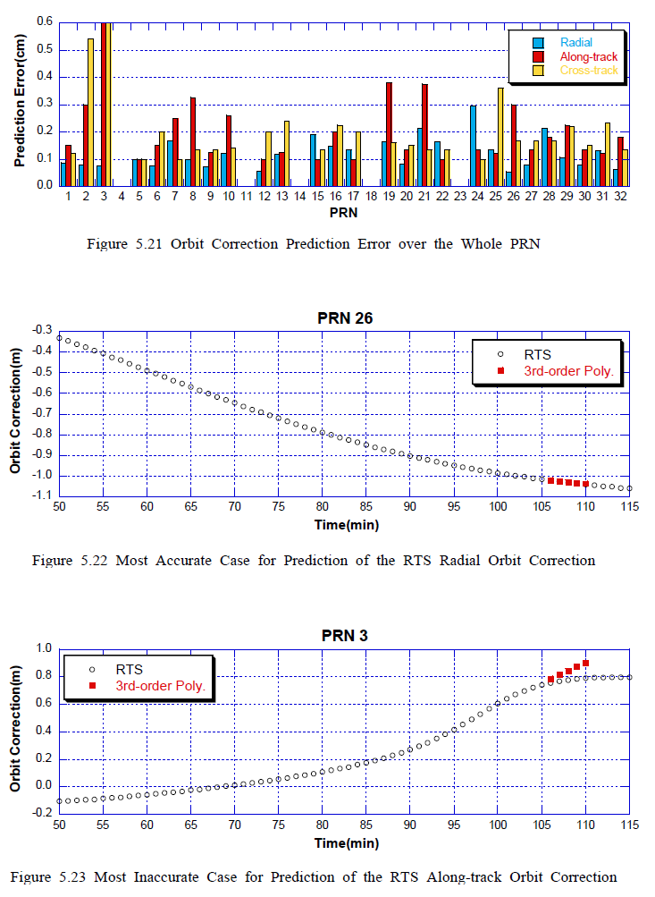
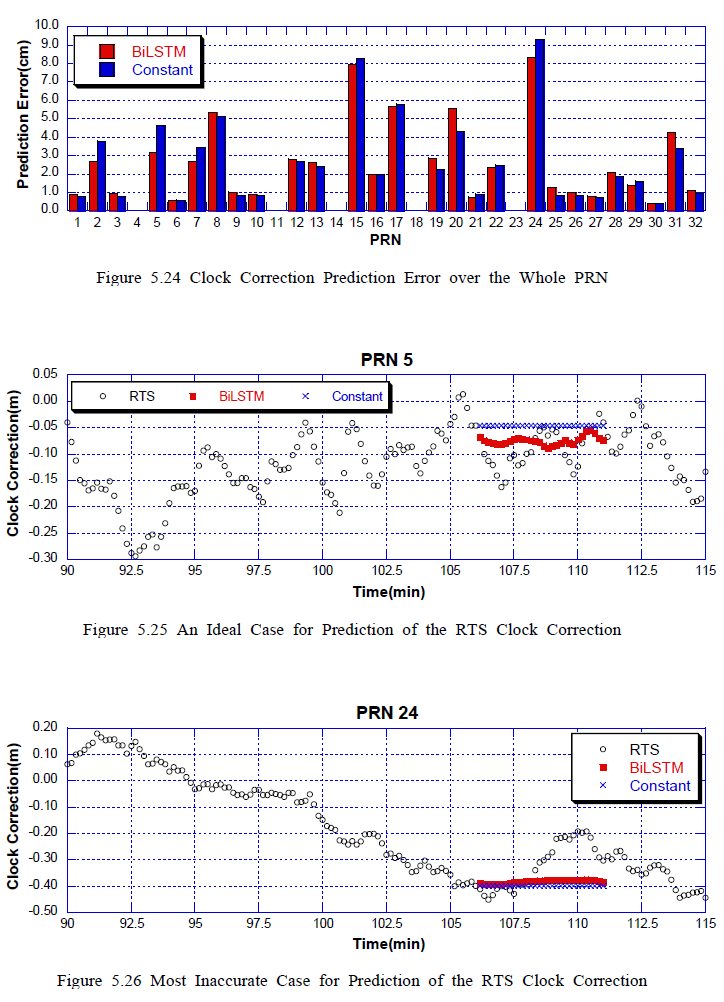
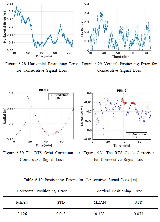
Prediction Results for Orbit(left) and Clock(right) Correction during Signal Loss.
The accuracy is 0.0534cm in the figure to the left in the middle, which predicts the orbit correction.
Based on the analysis of RTS Clock correction, the BiLSTM model is used for prediction of it.
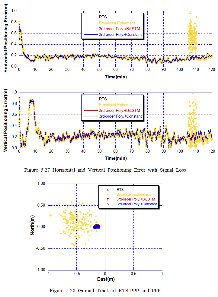
Left: Comparison of PPP Performance in a single signal loss for the whole test period.
Right: Comparison of PPP Performance in a single signal loss for 5 minutes.
The Optimization Result for Prediction: 3rd-order Polynomial model(orbit), BiLSTM(clock).
o Hardware Approach
- Porting
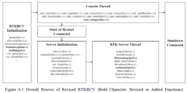
Functions were revised or added to the original program - RTKRCV, which is a CUI version of RTKNAVI
Configuration: Option(Initialization), Command(Console Thread), Signal Loss Detection and Prediction(RTK Server Thread).
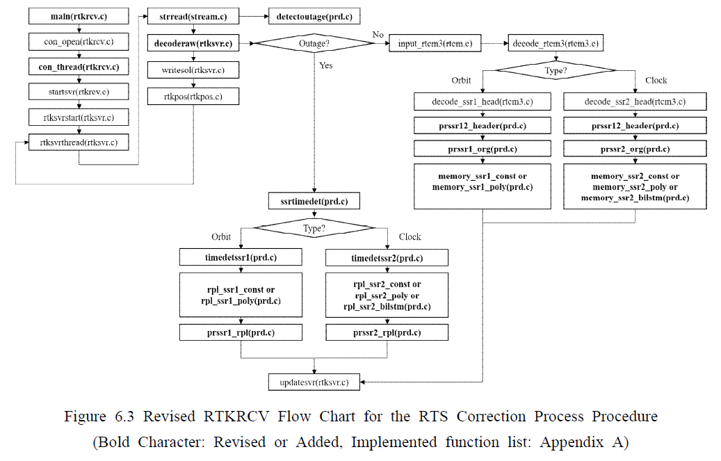
Left: A Flow Chart for Revised RTKRCV, as Featured by the Outage Detector, SSR Time Determinator and Correction Predictor in Replacement Functions.
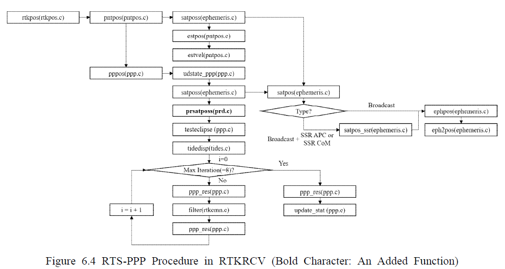
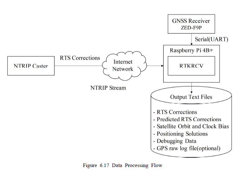
Right: The RTS-PPP Procedure in RTKRCV with the Logging Function for the Orbit Corrected by the RTS Correction.
- Detection
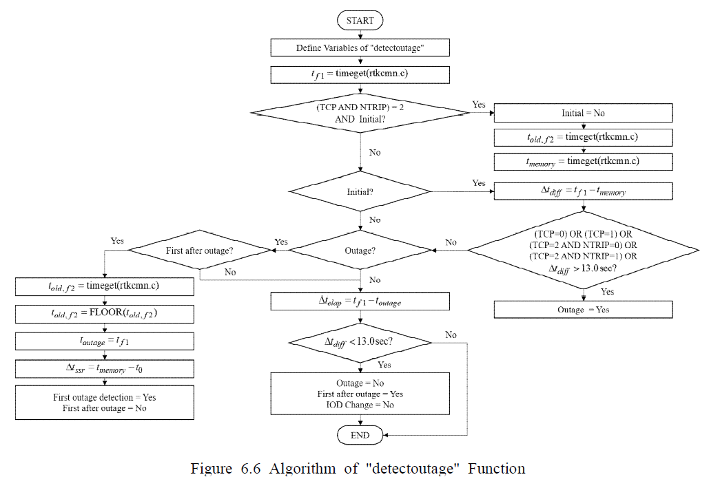
Left: A Flow Chart of the Outage Detection Algorithm.
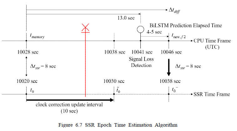
Right: A Diagram of Estimating the SSR Epoch Time.
- Prediction
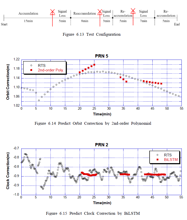
Left: Results for Prediction of the RTS Orbit and Clock Correction with the Test Configuration.
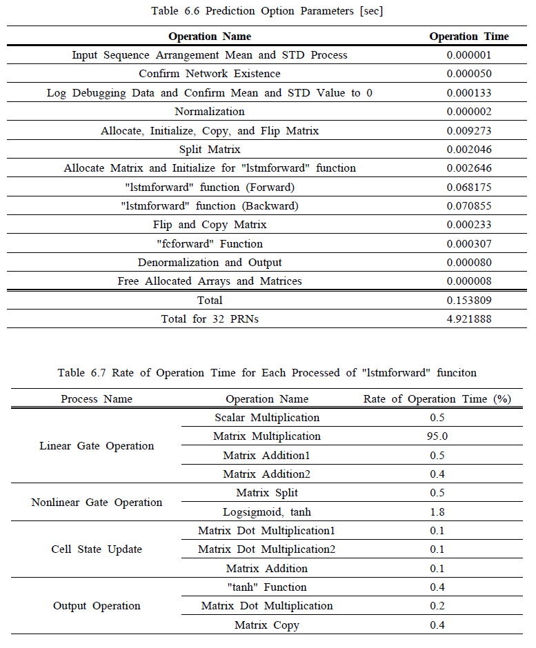
Right: BiLSTM Computing Time for Each Steps. It seems to be optimized for the computing time of the matrix operation.
o Operation Test
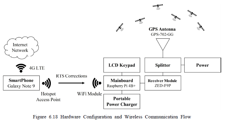
Left: System Architecture.
Right: Configuration of Experiment Equipments Based on the System Architecture(left).
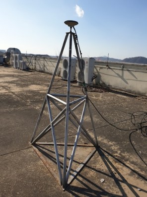
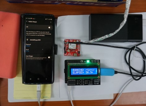
Left: Fixed GPS Antenna, NovAtel GPS-702-GG.
Right: Apparatus, where a diagram can be found upon.
This device was aimed for low-cost receiver(ZED-F9P) and portability.
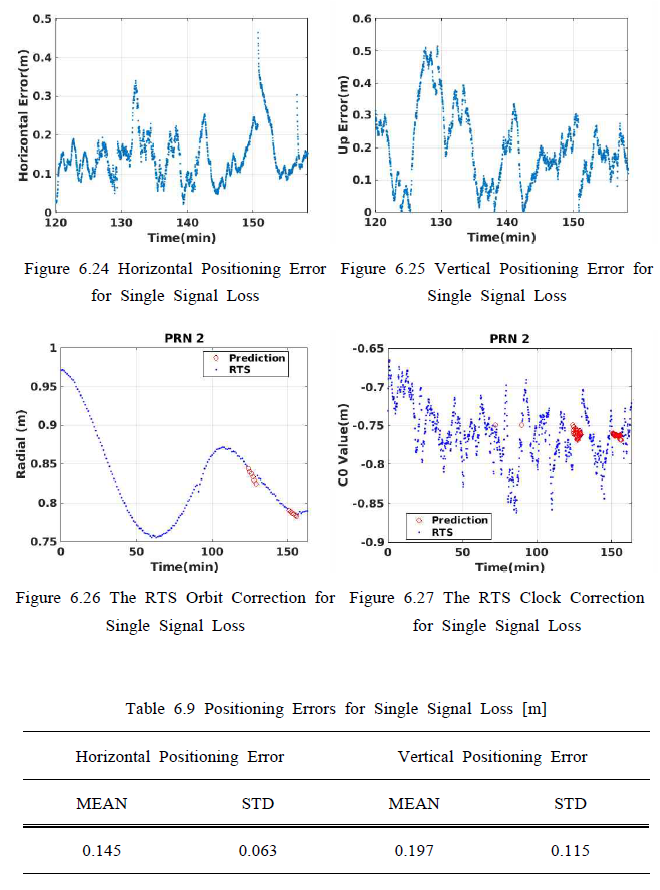
Left: A Case for Single Signal Loss with Overlength for the Prediction Length.
Right: A Case for Consecutive Signal Loss.
Operation tests of RTS-PPP were performed for stationary motion state by kinematic positioning mode. Those kept their precision in an outage with respect to the average appreciated.
o Discussion
A Kinematic Field Test is needed.